Showing posts with label Red Rubber Grease. Show all posts

Thursday, June 4, 2015

52600 miles: Nissin Four-Piston Callipers and front fork bushes rebuild

After 52,600 miles, 15,000 under my stewardship, the forks were leaking and a baggy feeling. The two-piston callipers had suffered over the winter and were binding. So I thought I'd give the front end a refresh. 

I did the brakes first. I thought I'd give the callipers from my dormant Daytona a bit of a birthday with a scrub up and use those for a while. That would allow me to spend some time on the Trophy two-piston callipers. The Daytona uses Nissin opposed-piston callipers, two per side of each disk (four per calliper, eight in total). This contrasts with the Trophy callipers, which rely on two pistons acting on one side of the disk, with sliding pins bringing a secondary brake pad into contact with the other side. Sliding pins are pretty notorious for getting sticky. Opposed piston callipers should be more robust, as long as corrosion does not creep behind the piston seals.  

Splitting one of the Nissin four-piston callipers,
and pleased to find it was in good shape
 When I split and dismantled the Daytona callipers, I saw that the anodised finish had been applied to the whole casting after machining. I'd never seen this before. The benefit is better corrosion resistance in the grooves where the rubber seals sit. So they didn't need too much work to clean up ready for reassembly with red rubber grease and a smear of copper grease on the edge of the pistons where they contact the brake pads.


I decided to replace the master cylinder piston and seals because they are 21 years old (the Daytona was made in 1994). They looked to be in good shape, with the exception of the dust seal around the piston. This had a small tear. I've see water accumulate behind these before with nasty corrosive consequences so it was worth changing this anyway.


Daytona disks stripped cleaned and centres repainted silver


 The forks were pretty straightforward to strip because I made up a tool to hold the Trophy's inner damper units when I did them first. These units are retained by a large allen-headed bolt through the bottom of the aluminium outer. The damper has to be held still with a hex-headed rod to undo the allen bolt. It can be a real pain without something that fits the hex. I found some big nuts - (30mm see next blog post) - and suitable threaded rod at an agricultural supplier. I locked the nuts against each other at each end of the threaded rod so they would not rotate on the rod and it worked a charm with a large adjustable spanner to keep it still as I cracked the thread on the allen bolt with a 3/8 drive Allen bit on a tommy bar.

There are two bushes in each leg: one is at the top of the aluminium outer, or 'slider', and the other is on the bottom of the stanchion. The bushes were easy enough to do, the top bush coming out with vigourous working of the stanchion in the outer, after removing a retaining ring, and using a small flat screw driver to spring open the lower bush to slide it off of the chromed stanchion. I had trouble plastic oil control rings that fit into the dampers - I bought the wrong ones for these forks. Doh! So I reused the old ones.
The bodywork always seems to come up well
with wax shampoo 
All shiny again, but more brakey!

Ride out in the dusk of a beautiful Spring day

Sunday, July 15, 2012

Mounting oil temperature and pressure gauges

The pressure and temperature gauge story so far: sensors installed, having sorted out the position of the oil pressure sensor so it wouldn't foul on the exhaust,  wiring harnesses made up to my satisfaction. Time to think through mounting the gauges themselves. The instruments on the mark 1 Trophy are mounted in a binnacle that bolts to the underside of the forks' top yoke. They are offset from the yoke and a bit of measuring suggested there would be room enough to squeeze in the the little gauges I'd bought.  

So the next question was how to mount them. With a bit more measuring, I could see an additional bracket would be possible to replace the bracketry they were initially fitted with. This new bracket would share the two M6 bolts that hold the main instruments in place. I'd already improved the firmness with which the main instruments are held in place so I was pretty confident about the security of this plan. I marked out my design on a bit of cardboard and cut it out to see if the idea would work in the space. 

The gauges came with a swivel mount attached to the front edge of their aluminium bodies. The only trouble with my plan was that the gauges would have to mount upside down because I'd need to attach them at the back of their bodies rather than the front. So I would have to reverse the guts of the gauges so my replacement bracket would screw to the rear edge instead, to solve the problem of the digits being upside down.

 So, idea demonstrated as feasible, I marked out the shape and holes I wanted on a 1mm aluminium sheet. I drilled the holes out before cutting with my jigsaw because it is much easier to drill into flat sheet than the something with bends in it. I decided to drill two possible mounting holes for the gauges so I could choose between two heights.


With the shape cut out, I clamped it in my pretend workmate and banged over the extensions for the gauges with a rubber faced mallet, then tidied up the roughness left by the jigsaw and drill with a my favourite fits.


 A trial fit showed the bracket was marginally too wide and the top edges of the gauges needed to move inwards and rearwards by between 5mm and 10mm to avoid fouling the top yoke and instrument binnacle.

I put a little bend into the aluminium to bring the gauges away from the binnacle (visible) and then another bend just inboard of the 90 degree bend to tilt the gauges inward towards the centre line of the bike (not visible).

I was now happy with the positioning of the gauges so needed to sort out the fact that they were upside down. I was also concerned that these car gauges might suffer in the rain. The electronics for the gauges are mounted on a small circuit board so they are on the opposite side of the mounting screw. Reversing this circuit board ran the risk of the mounting screw contacting the components. I solved this by cutting a piece of plastic sheet (actually the blister from the box the gauges came in) to insulate the electronics from the mounting screw. It was a bit of a fiddle to get it back in reversed with the improvised insulator but I got there with both gauges.

 I bought a box of o-rings in various sizes at an autojumble. I found some rings that were the same external diameter as the gauge bodies and coated them in rubber grease to help keep the water out. I gave my new bracket and the gauge bodies a coat of paint too.

 Here they are in place. I'm not sure about the purple anodisation. Purple and red aren't a great combination so I'll probably get the Smoothrite out again. Still, pretty neat, eh? They might even work ... ;-)

Wednesday, June 20, 2012

Pump, alternator and tidying up the front of the engine.W

Having refitted the engine covers, I was ready to install the alternator and water pump. The shiny state of these components showed up the rather tatty state of the front of the engine at the same time. So, despite my claims that I would focus on adjusting and lubricating from now on, I couldn't leave it.

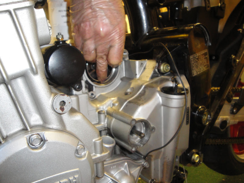
I've become fond of using red rubber grease every time rubber components are involved. In the case of the alternator, it was handy for keeping four rubber cush drive blocks in place. The drive works on four vanes on a sort of sprocket that is bolted to the alternator shaft. The cush drive blocks fit between these vanes and the drive, visible as a circular aperture behind my hand in the photo below. The blocks kept falling out of place before I could locate the alternator vanes. I found that sticky red rubber grease did a great job of keeping them put plus, I'm hoping, giving them an easier time in their shock absorbing role.


 Turning attention to the cooling system, I got new gaskets for the two hose spigots that the water hoses connect to. The curved one behind the cylinder block is for returning hot water to the pump. The small straight pipe near the left-hand sparkplug tunnel is for the cold water feed to the engine from the radiator.


Water pipe test fitted to the front of the engine, showing
slightly tatty 'before' state 
Front of engine after washing down with white
spirit to remove grease and road tar, then spraying
with VHT silver and clear laquor
I added stainless washers above and below the standard fibre washer that dampens engine vibration from damaging the water feed pipe from the pump to the bottom of the radiator.  The fibre washer I removed was pretty mashed up so I thought I'd give it an easier time this way. New copper washer on the M6 cylinder drain bolt. 


Comparing the left-hand side of the engine before (left) and after (right) my work. I guess it all amounts to going from 'tired' to 'as new' condition. Was it all worth it?

To me, yes, it is.

Wednesday, May 9, 2012

Refitting the swinging arm, rear shock and centre stand

The swingarm had suffered from scuffing towards the left-hand end. It also had pitting from corrosion in areas where water and salt had crept under the chain guard and gator which connects to the rear mudguard. I treated those areas with special metals primer, topped off with silver Smoothrite. When the mudguard and gator are replaced, they'll be hidden anyway - it's good for me to know they'll be protected from similar problems in the future. 
The main  suspension components for the swingarm include hollow spindles for two drop links that connect to the drag link. The spindles have grease nipples in their outer ends - these appear to have been used as intended.  The spindles fit through three short sleeves in the swingarm casting. These had suffered a bit. The drop links have needle roller bearings at each end and are both protected from the elements with decent seal arrangements.  The top bearings benefit from large steel and rubber seals, the lower bearings are looked after  by pressed-in rubber seals. All were in good condition. 
Drop links - Meriden-style
logo on these early castings

Needle roller bearing was in
great condition, visible here after
cleaning out the old grease with parafin

 I reassembled the drop links with new sleeves and a combination of Castrol LM for the needle rollers and Rock Oil rubber grease for the seals. Torquing up the spindles is a bit tricky - the trick is to use a socket for a 12mm spark plug because these are 18mm across the flats.

The chain has to be looped over the left-hand leg of the swinging arm first. The swingarm slides in between the frame outriggers and steel castings. The castings should be left loose at this stage - a bit of movement is helpful to get the swingarm positioned properly. The swingarm spindle is inserted from the left because it makes it easier for dealing with the chain. Stop when the spindle gets to the first steel casting. An alloy spacer must then be inserted between the steel castings. 


Alloy spacer in place between the two steel
castings. The return springs for the centre
stand are visible, hooked on to small
protrusions on the castings. 
 The rear shock is best mounted after the alloy spacer - there is very little room for manoeuvre when the shock is in place. I supported the rear of the swingarm with bungees looped over the frame. This helped maximised the room I had for wiggling the shock into position, and then to line up the shock's lower eye with the bottoms of the drop links for inserting the drag link spindle.   I put lots of grease on the edges of the drag link that would but up against the drop links and shock. There was a fair amount of corrosion on the drag link there, especially to the left of the shock mounting point. I'd seen this on all three of the drag links I'd looked at previously so it's well worth the trouble of slapping on the LM at this stage.

Inserting the drag link spindle from the right-hand side
through the right-hand drop link, shock lower eye
and then manoeuvring the left-hand drop link into place.

The large hex bolt with grease nipple about
to be wound in to the left-hand end of the drag link spindle. 
I decided to polish up the eccentric adjusters for the rear wheel. They were scarred by heavy-handed attempts to refit the rear wheel in the past. I got most of them out with wet and dry abrasive paper on thick pane of glass. Then I polished them with drill and mops. 


 The centre stand fits to the lowest holes in the steel castings. I found it easiest to attach the return springs by looping a 12mm ring spanner over the lower ends - it meant I could get a good grip to pull them over the prongs on the stand.

All sorted, ready for the rear wheel.