Showing posts with label front suspension. Show all posts

Sunday, May 19, 2013

Adjusting preload on front suspension

I had guessed at the best length of the spring spacer on my front forks, after deciding the standard spacer was making the front end too harsh. The standard spacer is 110mm long but, as my replacement springs are 20mm longer than the springs I took out, this was preloading the replacement springs quite significantly. So I made up a pair of 90mm spacers. These turned out to allow more sag than I wanted so I decided to add an additional packing for the replacement springs. Also, the 90mm spacers were from a narrower diameter tube than the standard spacer (which has a diameter of 38mm). 
90mm spacer shown loose in stanchion
 I decided to use o-rings to keep them centralized in the fork tube. I bought a Hilka O-ring kit some time ago and it included some that were just right.They made the spacers a snug fit in the stanchions so I have better confidence the forces will be centralized and distributedevenly.

Top 3mm disk being installed over 9mm spacer and lower 3mm disk
I added the additional length to the spacer I made up before with two 3mm thick disks and an extra section of tubing 9mm long. I cut the disks out of sheet aluminium with a drill attachment and a jigsaw: a very noisy business. It took a fair amount of filing to sort them out after the power tools but I was pleased with the result. This means the total spacer length is 86 + 3 + 3 + 9 = 101 mm.

I rode south to the Sammy Miller Museum today and was pleased with the result. The ride is firm but not overly firm. This is a matter of personal preference of course. It feels more controlled than with the 90mm spacer but just that bit more compliant than 110mm.
TriMoto 1200 outside the Sammy Miller Museum

Friday, October 19, 2012

Lowering front suspension

After riding my renovated Hinckley Triumph for a few weeks now, I'm forming a better impression of how it behaves on the road in various conditions: wet, dry, dual carriage ways, A-road and B-roads. Compared to my 900, the 1200 Trophy provides a much smoother and roomier ride. The power is delivered with less vibration, the bars are more upright, and the suspension rides over ripples and bumps more evenly.

DSC05653
The power builds more slowly at first but gets exponentially stronger with a noticeable woosh between 3500 and 4000. At 6000, the engine note takes on a harsher edge, vibration intrudes and the whole world seems to go into reverse. The bike is supremely stable at all times. However, the steering is noticeably slow compared to my Daytona. The effect is a swoopy bend swinging experience that adds to the sense of smoothness. I could wax lyrical Jaguar style: grace, pace and space.

DSC05654

I thought I'd experiment with the degree of fork pull-through. The effect of more pull-through would be to marginally change a number of things that can influence the steering. It will reduce the front ride height, lower the center of gravity, steepen the steering angle, reduce the trail, and I'm pitch me further forward an inch. This should make the bike respond more quickly to steering input. Triumph list a range of pull-through settings for different T300 models. They are measured from flush with the top yoke face to the top of the steel fork tube, just below the fork top nut:
  • Trophy, Trident & Sprint to      VIN 29155: 25mm
  • Trophy, Trident & Sprint from VIN 29156: 20mm
  • Daytona & Speed Triple to       VIN 29155: 28mm
  • Daytona & Speed Triple from  VIN 29156: 0mm (flush)
I had already allowed an additional 10mm (total 35mm) of pull-through to compensate for the fact that I'd installed 20% stiffer springs. I'd calculated that the difference in spring rates would mean so doing would maintain approximately the standard ride height. So this time, I pulled the forks through an additional 14mm (24mm), or just under and inch in total above the base figure.

Extra24mm

Although as I say such a change will result in a very small difference in each of the relevant parameters, the nett effect can be noticeable. Would it be for me?

Stanchions proud of handlebar mountings


The answer is yes. I'm afraid it is still a case of impressions rather than hard data but I'd say my Trophy 1200 feels very very similar to the Daytona 900 like this. There is no hint of delay now between input at the steering and effect on the machine. Dropping the front by an inch means the seat is about half an inch lower. Although it means my hands are an inch lower, the angle of hands to forearms, shoulders etc. is unchanged. The ride feels that bit more direct.

Some issues to be aware of:
  1. it is much harder to get the bike onto its center stand now. Far harder. Herniating, I shouldn't wonder.
  2. the belly pan is an inch closer to the road - sleeping policemen must be treated with caution, bumping up curbs is totally out (a good thing not to be tempted to do). 
  3. the steering is more sensitive to running over cats eyes now. 
 I can live with all of these things for now.

SitsLower

Thursday, July 5, 2012

Pitted fork repair, Sprint Manufacturing 20% uprated springs, and front wheel refit

With the forks removed, I could see how much pitting was present on the stanchions - a lot, as it happens, although each individual pit was pretty small, maybe up to 1mm across.


I decided to try filling them with Chemical Metal epoxy paste on the grounds that, well, it just might work. If not, I'll get them reground and hard chromed. So I degreased them with cellulose thinners and dug as much of the dirt out of the pits as I could with a pin, wiping as i went. Then I mixed up the Chemical Metal a bit at a time and covered the affected areas. It goes off very quickly (about 5 mins) so I had to repeat the process lots of times. 

After leaving it to cure completely overnight, I trimmed back the excess filler with a sharp blade and rubbed the stanchions down with 800 grade wet and dry paper. The finish was smooth and reasonable. I've no idea how robust it will be. 


I'd decided to fit some 20% stiffer replacement fork springs from Sprint Manufacturing. I carefully measured lengths as I went. First, the difference between fully compressed and fully extended is about 145mm. Second, the standard spacer is 110mm. 


The springs I removed were 470mm in length (the shorter, darker spring in the picture below). I would say the 'standard springs', which I believe them to be, but who knows whether a previous owner changed them. The Spring Manufacturing springs were about 490mm in length. I could have cut the spacer down accordingly (to 90mm) but decided I would treat it as an additional 20mm preload to start with and then shorten if required later on. This meant being very careful in compressing the springs to refit the top nut but they went together well.

I decided to try comparing the spring rates. No pics I'm afraid but I did this by placing an old kitchen scales upside down on each of the springs and then compressing them for 1cm. I was surprised to find that the Sprint springs were about 6kg per cm whereas the ones I removed were 6.5kg per cm. In other words, harder. So maybe they aren't the originals. However, the Sprint springs have two pitches  whereas the springs I removed were evenly wound along their entire length. The manual indicates that the originals should be twin rate. I decided I'd try to see what the rate of the Sprint springs are when the close-wound section binds. I did this by clamping the spring in my workmate just above the close-wound section and repeating the scales trick. This time, it showed a rate of 7kg per cm, so about 17% stiffer by my imprecise measurements - close enough to Sprint's claim for me to believe all is in order.


 Forks reassembled, I decided to fit a pair of stone guards. The clamp just above the dust seals. Hopefully, they'll help to keep the Chemical Metal repair functional for a little while at least.


I decided to pull the forks through the yokes slightly more than standard because the stiffer springs would make the bike ride slightly higher than normal, marginally slowing the steering geometry. Again, it's an experiment. The fact that I now know the difference between full extension and compression means I can adjust the down some more as long as I leave at least 145mm between the bottom yoke and fork seals.


I found that the front wheel axel was rusted internally. There is a plastic bung on the left hand end that had been damaged, allowing water ingress. So I cleaned it up with a drill and thin wire brush, primed and painted it before coating the bung in waxoil and refitting. I also gave the front axel nut a birthday.


 I like polishing. The fork top nuts and speedo gearbox gave me a chance to break out the Solvol and bling it up :-)


 Plenty of LM grease on the axel and the wheel is back in place. The axel can be held still with a tommy bar through the left hand end whilst the nut is pinched up. There was zero clearance between the fork legs and the wheel spacer (left) and speedo gearbox (right) so it was a performance getting the wheel in place. I managed it in the end by slackening the fork clamp bolts in the lower yoke and slightly twisting the sliders.

For torquing the axel up, it is necessary to tighten two clamp bolts in the left-hand fork leg so the axel doesn't rotate. The two clamp bolts in the right-hand leg can then be torqued too.


 Handlebars and clocks loose fitted, starting to look like a bike again.


Thursday, June 28, 2012

Steering head


Having sorted out the rear suspension some weeks ago, and been doing stuff in the middle of the machine more recently, it was time for me to do something with the front end. 

The World of Triumph parts website for the mark one Trophy is great for exploded diagrams. I've put links in to them in some of my earlier posts without saying much about their utility for the amateur spannerman, such as myself. I think it's a fantastic resource, not only for seeing how things are supposed to go together but also it normally lists sizes of the fasteners as well. So it's easy to find replacements for those that are beyond the pale. However, mysteriously, this particular diagram and parts list does not include headstock bearings. How mad is that? Fortunately, as the pics below show, I don't need to replace mine anyway.

Dismantling front wheel, forks and the steering head (yokes and bearings) was really straightforward - no explosions involved. I supported the bike with a plank under the sump, resting on bricks so the front wheel was just clear of the ground. There were no stuck or rounded bolts to deal with, and no obvious corrosion - at least, not at first.

The steering head is supported by taper roller bearings. The top bearing (marked Koyo 32005JR) drops onto its tapered seat and is clamped in place by a threaded collar. 

Bottom steering head bearing
before waxy old grease
was cleaned out ... 
... and again after cleaning.
Mucky residue visible in the pan.
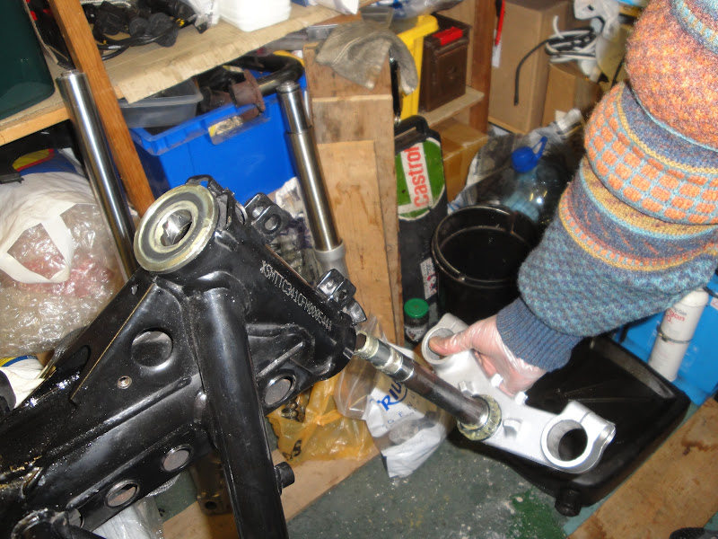
 The bottom bearing is an interference fit on the steering stem, flush with the bottom yoke. Both were greased but it had a waxy consistency - probably as old as the bike. 22 years old, that is: the underside of the bottom yoke is marked 20th of December 1990. So I flushed it out with a paraffin in my trusty stainless pan and a toothbrush.


The steering stem has a strange rectangular slot at its midpoint. I've no idea what this is for. My best guess is that it is something to do with the manufacturing process, maybe for clamping for insertion into the bottom yoke.
 I filled the cleaned bearings with grease by wiping fresh grease onto the outer surface of the rollers, spinning the bearing to carry some of the grease inside, then wiping on some more and repeating the process until the rollers were all rotating out in a properly lubricated condition. The same technique works equally well for top and bottom bearings, it's just a bit more cumbersome with the bottom one.


The top bearing just drops into its tapered seat in the top of the steering head. The seat was in great condition. Hooray! The bottom seat was also in fab condition. There is a rubber dust seal beneath the bottom bearing - it did a good job of keeping the grease in place so that's probably why. The steering stem passes through the steering head and top bearing, and is then retained in place by a threaded aluminium collar.

 The collar on these early bikes is intended to be turned by hand to a point where vertical movement in the bearings is just eliminated, and no more. It is a judgement, this, made complicated by the stickiness of the grease. After two or three tightenings and slackening off, I was happy with the level of tension I'd put into them and the left-to-right movement of the steering action. So I lightly torqued up the M6 pinch bolt to the specified level.
 The top yoke holds the ignition switch/lock assembly. It is bolted in place with security bolts so cannot be removed without awkward drilling. Consequently, the top yoke has to be installed twisted about 80 degrees from straight ahead so the lock misses the frame bracket with which it will later engage. It fooled me at first. The top yoke is ultimately torqued up when the forks and wheels are installed and checked for alignment.


Next step, strip clean and inspect the forks.