Thursday, July 19, 2012

In praise of Carlo

As I explained in one of my first entries, the inspiration for this site is my amazement at the re-emergence of Triumph in the early '90s. This was an extraordinary achievement for a small team of engineers and a man with a vision (John Bloor). They started with a blank sheet of paper and drew in all the best qualities of motorcycle engineering in the late 1980s to create a real-world, real man's motorcycle for the 1990s. However, I also want to acknowledge the enthusiasm of an Italian who I'm sure would recognize my feelings about the Trophy 1200: Carlo Talamo, one of the three guys behind Numero Tre in Milan (along with Roberto Crepaldi and Max Brun).

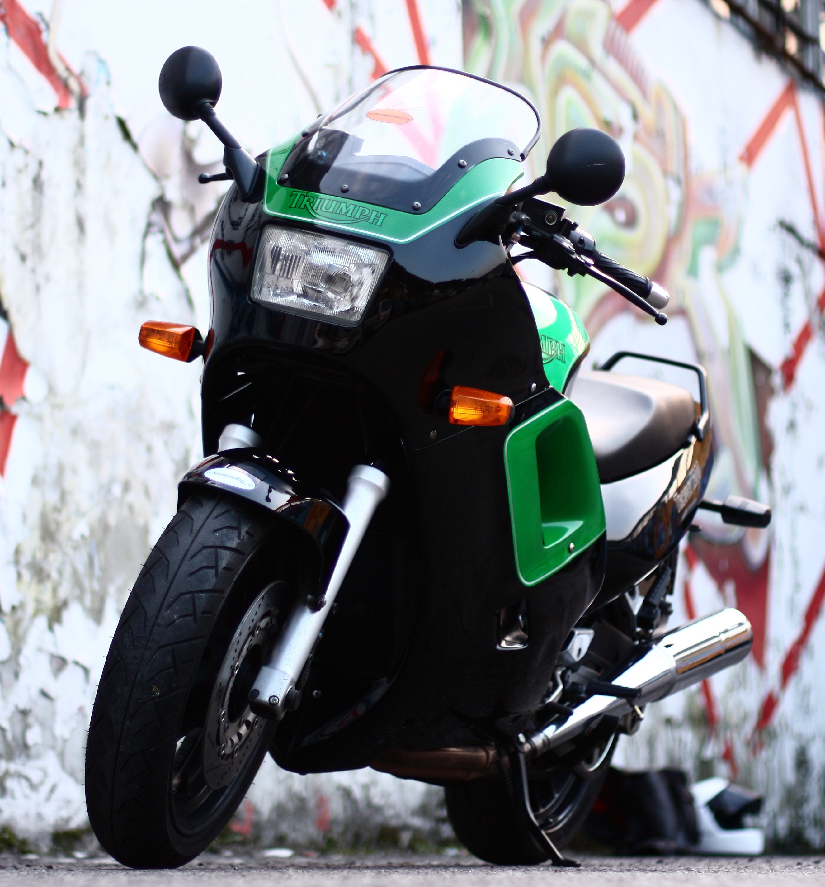
Although his passion was ignited more by the triples in the range, he imported the first Trophy 1200 into Italy and that was a signal experience. The whole story of the bike is told on the Federotriple website. Carlo swapped the forks and brakes for Daytona items and had the bike repainted in black and green: as you can see in the photo below, a pretty stunning choice. It was the first Triumph to be treated this sort of special attention and so a landmark machine in the history of Numero Tre.


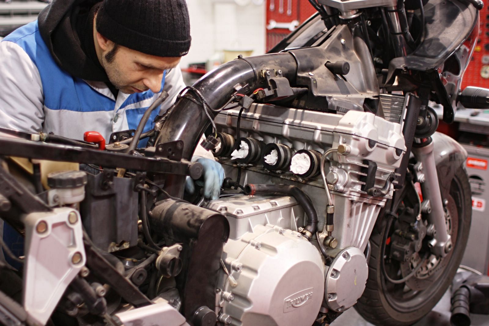
The bike was then given to Marco Marchisio as a mark of gratitude for his long association with Carlo. The story goes on to explain that, long after, Marco returned it to Numero Tre as an important piece of history, whereafter it was returned to service by one of their mechanics in 2010. 


The story and the images of its recommissioning helped to inspire me to turn my musings about bringing a 1991 Trophy 1200 back to its former glory.   I dream of the day when I too can bring you a video of the moment when she speaks again. 


Perfetta!

Monday, July 16, 2012

Exhausting tales

The exhaust was very clean externally, as the pic below shows. It has two pairs of stainless steel headers, connected with a link pipe that runs beneath and behind the sump. 

The link pipe had a big dent - probably caused by bumping up or down a kerb. The silencers are high quality chromed items, made by Motad for Triumph. 


The exhaust is bolted to a bracket via a rubber insulating bung.

The bracket in turn locates on two of the bolts at the rear of the sump. The lugs on this bracket were snapped off. I don't know for sure but I'm guessing it was because the silencers were stuck on the headers and possibly attempts to wrestle them off had resulted in the snapping of the bracket's lugs. 


I couldn't easily tell the internal condition of the silencers so I knew I'd want to get them off the headers at some stage. It made life hard for me to test fit the pipes around the sump because the length of the system is hard to manoeuvre and the silencers themselves are very heavy.

Attempting to test fit the exhaust was hard work with the
silencers stuck to the headers
 After many months of soaking in WD40, the silencers still refused to give up their grip on the exhaust headers. I decided, with regret, that I would use my minigrinder (Dremel clone) to extend the slots in the end of the silencers to allow me to lever them loose.
Extending the slots in the silencers with a mini grinder. 
I clamped the silencer in my pretend workmate, using a towel to protect the chromework and improve the grip. It kept it all steady whilst I made the cut and then twisted the headers out.

 The right-hand headers and silencer were harder to do than the left-hand side. When I did finally get the headers out, it was clear why.


 The inside of the junction had rusted badly though this wasn't visible from the outside. Rust expands and, beneath the right-hand silencer clamp, had the effect of gripping onto the header ever more tightly. So, whilst extending the slot with my grinder released the pressure, it also just showed up the extent of the rust at this point and so a need for me to replace it.


I was then able to clean off the dirt and surface rubbish with a wire brush on my electric drill. The stainless steel is great quality - it responded well to this treatment. I was also able to reduce the dent in the lower edge of the link pipe using a six-inch extension bar from my 1/2 inch drive socket set. I hammered it in and then levered against the inner section of the dent. It's not a perfect repair by any means but will allow the passage of exhaust gases in the way the designers intended. 

Finally, treatment with Solvol cleaned of the residue left behind by the wirebrush treatment and brought out the colour of the stainless rather nicely. 


I removed the old exhaust gaskets with a small chisel, working down wards and assisted by a little hammer. Great care is needed not to put gouges in the sealing surface. As soon as the chisel had bent the old gasket out by a few millimeters, I was then able to lever out the ring.

 I used copper grease to hold the new copper gaskets (from Sprint) in place whilst I fiddled about with the exhaust headers to get them into position. I put the right-hand pair on first because these are the ones fitted with the link pipe bracket. I positioned the link pipe bracket first and then, holding it in place with my left hand, lifted and knocked the headers into their recesses with my right. The bracket is then retained with an M8 35mm stainless bolt.
Stainless steel M8x35mm bolt retains exhaust headers
at the rear of the sump.
 I had previously replaced the exhaust studs with stainless and used stainless nuts, spring and plain washers to retain the headers.
Oil cooler dangling in front of the headers.

Looking more and more like a bike engine every week.

Sunday, July 15, 2012

Mounting oil temperature and pressure gauges

The pressure and temperature gauge story so far: sensors installed, having sorted out the position of the oil pressure sensor so it wouldn't foul on the exhaust,  wiring harnesses made up to my satisfaction. Time to think through mounting the gauges themselves. The instruments on the mark 1 Trophy are mounted in a binnacle that bolts to the underside of the forks' top yoke. They are offset from the yoke and a bit of measuring suggested there would be room enough to squeeze in the the little gauges I'd bought.  

So the next question was how to mount them. With a bit more measuring, I could see an additional bracket would be possible to replace the bracketry they were initially fitted with. This new bracket would share the two M6 bolts that hold the main instruments in place. I'd already improved the firmness with which the main instruments are held in place so I was pretty confident about the security of this plan. I marked out my design on a bit of cardboard and cut it out to see if the idea would work in the space. 

The gauges came with a swivel mount attached to the front edge of their aluminium bodies. The only trouble with my plan was that the gauges would have to mount upside down because I'd need to attach them at the back of their bodies rather than the front. So I would have to reverse the guts of the gauges so my replacement bracket would screw to the rear edge instead, to solve the problem of the digits being upside down.

 So, idea demonstrated as feasible, I marked out the shape and holes I wanted on a 1mm aluminium sheet. I drilled the holes out before cutting with my jigsaw because it is much easier to drill into flat sheet than the something with bends in it. I decided to drill two possible mounting holes for the gauges so I could choose between two heights.


With the shape cut out, I clamped it in my pretend workmate and banged over the extensions for the gauges with a rubber faced mallet, then tidied up the roughness left by the jigsaw and drill with a my favourite fits.


 A trial fit showed the bracket was marginally too wide and the top edges of the gauges needed to move inwards and rearwards by between 5mm and 10mm to avoid fouling the top yoke and instrument binnacle.

I put a little bend into the aluminium to bring the gauges away from the binnacle (visible) and then another bend just inboard of the 90 degree bend to tilt the gauges inward towards the centre line of the bike (not visible).

I was now happy with the positioning of the gauges so needed to sort out the fact that they were upside down. I was also concerned that these car gauges might suffer in the rain. The electronics for the gauges are mounted on a small circuit board so they are on the opposite side of the mounting screw. Reversing this circuit board ran the risk of the mounting screw contacting the components. I solved this by cutting a piece of plastic sheet (actually the blister from the box the gauges came in) to insulate the electronics from the mounting screw. It was a bit of a fiddle to get it back in reversed with the improvised insulator but I got there with both gauges.

 I bought a box of o-rings in various sizes at an autojumble. I found some rings that were the same external diameter as the gauge bodies and coated them in rubber grease to help keep the water out. I gave my new bracket and the gauge bodies a coat of paint too.

 Here they are in place. I'm not sure about the purple anodisation. Purple and red aren't a great combination so I'll probably get the Smoothrite out again. Still, pretty neat, eh? They might even work ... ;-)