Wednesday, July 3, 2013

Alternator - sheered bolt and squashed cush rubbers

My Daytona had been rattling for ages from beneath the carbs. I'd noticed it only did this when the alternator was not under load. As soon as I switched the lights on, the rattle went away. Amazing but true. The light switch was a rattle controller! 

Reading around, I'd found people with this problem saying it was to do with a worn alternator cush drive. On a visit to Sprint, I talked to Trevor about it and he said it was far more likely to be a problem with a bolt that holds a rotor onto the alternator itself. It turned out to be both ...

The pictures above show the bolt loose on the driven rotor (23 in the schematic) and the replacement bolt next to the remains of the original to show how much was left in the alternator rotor. The drive and driven rotors have four vanes the fit into one another, cushioned by eight rubber segments as the 'cush drive' (number 20 in the schematic below).
Parts schematic for alternator drive gears
 The pics below show the worn cush drive rubbers in the drive rotor and comparing them to the new replacements.


I'd also had some trouble with the starter motor so pulled that off at the same time as removing the alternator. This meant draining the coolant because the rear coolant hose runs from the back of the cylinder block to the pump and obscures the starter.

Draining the 900's coolant - looking grubby ...
... but the black finish always comes up really well with degreaser and a bit of gentle agitation
The bolt that retains the driven rotor is 'encapsulated', meaning it comes coated with a vibration-resistant coating. As a result, it was hard work to get the remains of the original bolt out. I had to drill it right through. The main trick is getting the drill bit central in the remains of the old one and holding the work still. I don't have a pillar drill but a Record drill stand and press vice. The alternator is a very awkward shape all the same so I had to put a lot of packing around it to get the press vice to grip.
Drilling out broken M6 bolt with a 5mm HSS bit

After drilling and cleaning threads with a tap

 I'd done a fair job but the internal threads were clipped by my drill. Fortunately the encapsulation is meaty enough for me not to worry about that too much. I was able to torque it up carefully to the recommended level so all looks well.

Torquing up the replacement bolt, holding the driven rotor with an adjustable spanner
The replacement cush rubbers make for a close fit between the drive and driven rotor. I held them into the drive rotor with red rubber grease. It was a fiddle to line up the vanes on the driven rotor to get the alternator back in place but eventually went in with zero slop.


Mission accomplished.

Tuesday, July 2, 2013

A bit of love for my Daytona

 My Daytona has been remarkably robust against the rigours of year-round biking but was overdue for a bit of TLC. Although the headers are supposedly stainless steel, they had a black-chrome overlay from the factory. The 1994 Daytona's exhaust system is three-into-two-into-one-into-two and is in five parts: three-into-two header, two central link sections that join beneath the sump, and two silencers.

 The finish of the headers and central link sections had suffered pretty badly over the 71000 miles and 18 years. It was actually fine close to the exhaust ports, where the radiator has shielded it from the weather. Beneath the line of the oil cooler, the headers get a torrid time with road muck and spray blasting at them from the front wheel.
Stainless headers? Doesn't look like it here
My Trophy's exhaust is clearly stainless and had responded well to a rough polish with a brass wire brush on my drill. I remember they had a reddish brown deposit in places, especially around the link pipe that runs under the engine. It looked like rust but it came right off with the drill brush treatment, leaving a shiny silver finish. I hoped I might get a similar effect on my Daytona so got busy. It wasn't anywhere near as satisfying this time. It appeared as though the plated finish had been mainly corroded away, leaving a rough surface over most of the forward downpipes and the two collectors.

 To shift some of this, I had to use an angle grinder with a steel wire brush. This combination made good progress  - not perfect  but the metal work so revealed was perfectly sound and maybe could qualify as stainless steel.

Exhaust downpipes and central collector after angle grinder treatment
I had previously refurbished my Daytona's silencer link pipes with VHT black topped off with VHT clear and was very pleased with the result. It looks a lot like the original black chrome finish and had come through last winter intact. The finish I obtained is obviously nowhere near as hard as chrome but it does seem to be reasonably robust so far. I had some VHT clear left over from another job. I would have used VHT black again but didn't have any left. 

I'd read somewhere online that barbecue paint can work if it is cured properly so decided I'd give it a whirl - seven pounds from HomeBase on a 15% off weekend. The VHT clear might help to keep it in place. If it doesn't work, I'll try something else. As it happens, my home painting efforts on the Trophy haven't been a great success. Maybe I'll get lucky this time.
Headers coated with BBQ paint
 Before applying the VHT clear over the barbecue paint, I wanted to make sure the thinners were gone and the black coating was at least partially cured. So I used my hot air gun on its low setting to heat up the pipes from the inside. I blew air in through each of the five openings (three headers, two silencer exits) in succession, switching each one as soon as I saw smoke coming off of the pipe concerned. I went around each one twice and then left it to cool for an hour.
Refinished headers: will they cope with the heat of normal running? And winter salt?
 I painted the VHT clear over the BBQ paint by applying just enough to get a shine first pass and then immediately going over the whole thing for a second time. I made sure I got plenty around the collectors. Then I left it 24hours before using my heat gun again in the same way as with the BBQ black. After cooling again, I reinstalled the three M6 bolts that blank off sensor holes with copper grease, torquing to 10NM per the factory manual.
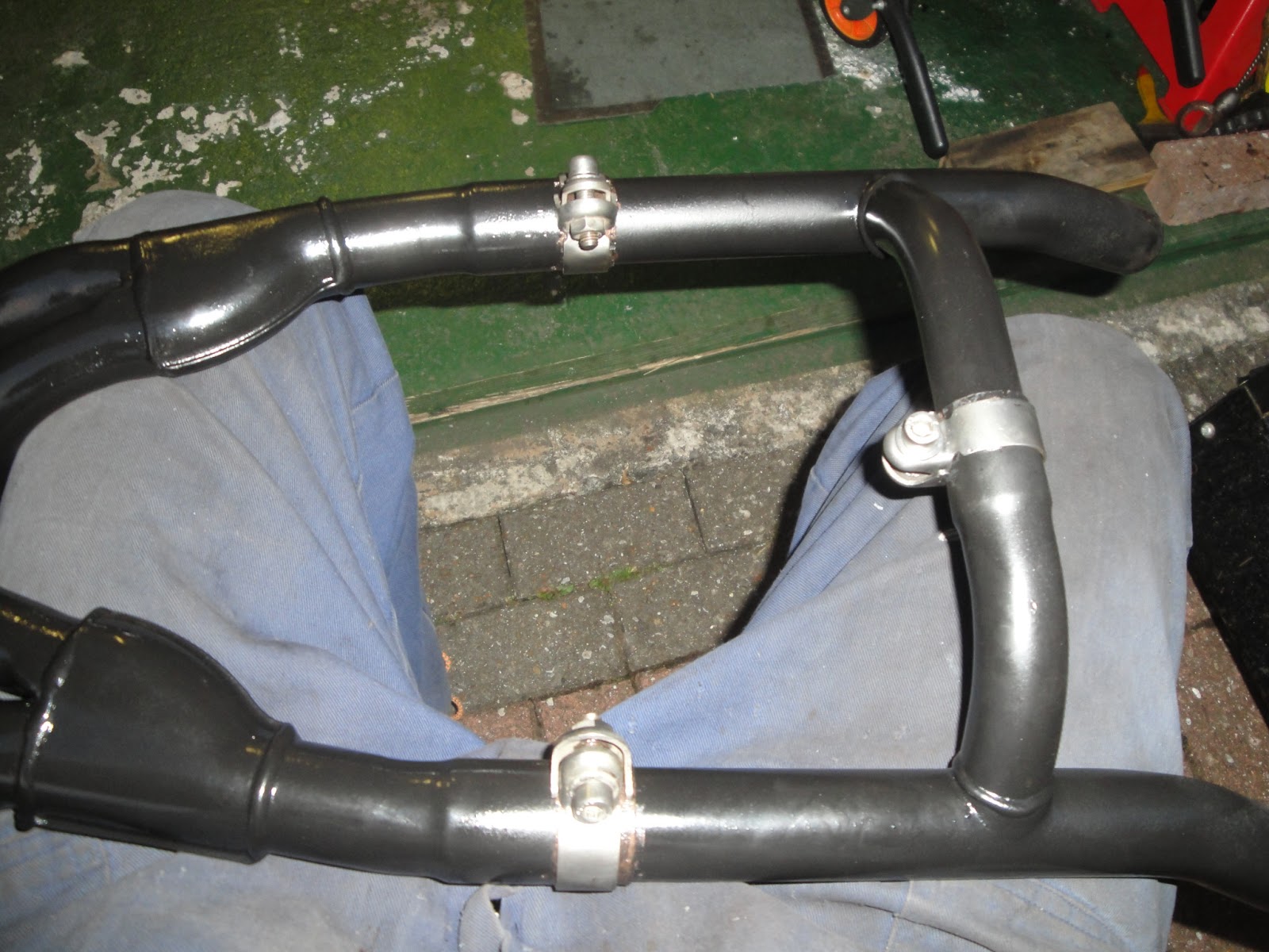
Three exhaust pipe sections back together with stainless clamps
The exhaust pipes are in three sections held together with stainless steel clamps. These clamps came up beautifully. I used a smear of copper grease around the joints of the header sections and inside the clamps to help it all go back together with minimum fuss.

I'm almost too pleased with the way the whole thing has come up. I might try to make up a shield for the headers to stop direct spray from the front wheel blasting them next winter.

Thursday, June 27, 2013

79mm nikasil liners compared to 76mm iron liners

Trevor let me take some measurements off of a T595 liner. I didn't have my camera with me so I can't post pics of it. The pictures below are from an old T300 liner I have had for ages. There are three important circumferential measurements: the depth of the spigot that fits into the top crankcase, and two distances across the upper portion of the liner. There are two of these because two sides of the upper surface are machined flat to allow the set of liners to fit side by side in the crankcases.
Spigot measurement; machined flats visible above


 I made a diagram to show how the liners compare. The nikasil liner for the T595 79mm piston looks very different from the iron liner pictured above. The ally casting includes vertical flutes in the upper portion, presumably to add strength and to aid in heat dissipation. The upper and lower circumferences are wider, as expected but not by a great deal. The lower spigot is 84.5mm compared to 82mm - so 2.5mm would have to be machined out of the upper crankcase for them to fit. However, the flats in the wider part of the casting make it effectively identical - 87.5mm compared to 87.2mm. In fact, that difference could just be down to my inexpert use of the vernier caliper.
Comparing dimensions of T300 iron and T500 nikasil cylinder liners

I also measured the distance across the top crankcase to make sure the wider nikasil liners would fit without having to thin down its walls - something I would worry about. It is 105mm so no problems there. I'll measure up the internal dimensions again when I manage to get the liners out of my 2001 Trophy 1200 engine.

These other pictures show the gunk around the iron liners in the 2001 motor. It appears to be an oily carbon paste. However, the bores look to be in very good condition. Most puzzling.