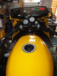
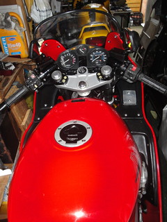
My fuel tap on my 1994 Daytona refused to turn off - petrol poured out regardless of tap position. The tap has three positions - on, off and prime. On and off are supposed to be controlled by a vacuum operated diaphragm that pulls a valve open when the engine is running. Prime holds the valve open via a cam in the tap so is the only position that should let fuel out of the tap with the engine off.
I managed to break the plastic knob when I was removing it. I had the 1991 Trophy one so could use it for the time being. The plastic knob engages with the aluminium fuel selector casting through a flat cast into its circular recess. This flat was the part that broke on the 1994 plastic knob. The 1991 one has the flat 90 degrees from the 1994 version, meaning the visible pointer on the outside of the plastic knob does not point down for reserve, back for on and up for prime. Instead, it points forward for reserve, down for on and back for prime.
 |
| Rebuild kit from Sprint Manufacturing |
 |
| Extracting tap from tank |
I got a
tap rebuild kit for £24 from Sprint Manufacturing. It includes two new springs (one to hold the diaphragm closed when the engine is off, one to keep the selector valve in tension so it returns from the prime position), four new screws, a diaphragm, a rotary oil seal and two shaped rubber grommets to seal the tap body against the tank.
The body of the tap is held on to the tank with two long M6 screws that pass through the selector housing and fuel filter housing to engage with captive nuts.
Fuel systems don't like grit so it's important to have somewhere clean to do the job. I have an old set of stainless steel camping pans for jobs like this.
 |
Vent hole (indicated byscrewdriver
tip) to allow diaphragm
to pull valve out when the
engine is running. |
 |
Removing diaphragm housing,
diaphragm valve closing spring
visible in the centre of the picture |
The diaphragm is housed in a chamber at the rear of the tap. The cover is retained by four M4 Philips screws. It is likely to pop off under the pressure of the larger of the two springs in the tap body - get ready to catch it when it goes.
There is a vent hole at the bottom of the diaphragm chamber, behind the fuel selector mechanism. I think my problem was probably dirt ingress through this vent hole interferring with seating of the diaphragm valve.
 |
Aluminium plunger with o-ring
under diaphragm |
 |
| Diaphragm valve seat location |
The diaphragm is actually two diaphragm components that attach to an aluminium plunger with an O-ring at one end. The two diaphragms fit either side of a plastic collar. There is a hole in the diaphragm that locates over the vent hole - a raised bump in the plastic collar helps to make sure it is round the right way on reassembly.


After pulling the diaphragm housing apart, it was very clear that dirt certainly could have been responsible for the problem. So a thorough clean was required.
There were traces of corrosion in evidence too so it carefully (there's a word) rubbed the sealing surfaces back with wet and dry on a foam sanding block.
 |
| Cleaned and ready for reassembly |
I used silicon grease sparingly on the sealing surfaces, eased the new diaphragm into its plastic collar then, checking that the vent holes were aligned, installed the new spring and tightened down the M4 screws.
 |
| New (left) and old (right) diaphragms |
 |
Installing new diaphragm, making
sure the vent hole is aligned to the
matching hole in the new diaphragm |
 |
With retaining screws released, the
fuel selector is pushed up by the small
screw on the prime operating rod
and can be lifted out.
|
The fuel selector is made of two parts, one an aluminium casting and the other a plastic component that it turns inside the top body. The aluminium part is held into the tap body by two screws. These screws have plain ends that fit into a track that is cast into the ally selector - they twist off centre to force the tap in when turned to the prime position. This is actually what makes prime work because a long steel rod pushes through the centre of the tap onto the diaphragm valve when this happens, thereby pushing it open.
 |
Fuel selector pushed into place and retained by screws.
The fuel selector positions are cast into tap body - these make
sense with the 1991 tap but don't match up for the 1994 tap |