Thursday, June 28, 2012

Steering head


Having sorted out the rear suspension some weeks ago, and been doing stuff in the middle of the machine more recently, it was time for me to do something with the front end. 

The World of Triumph parts website for the mark one Trophy is great for exploded diagrams. I've put links in to them in some of my earlier posts without saying much about their utility for the amateur spannerman, such as myself. I think it's a fantastic resource, not only for seeing how things are supposed to go together but also it normally lists sizes of the fasteners as well. So it's easy to find replacements for those that are beyond the pale. However, mysteriously, this particular diagram and parts list does not include headstock bearings. How mad is that? Fortunately, as the pics below show, I don't need to replace mine anyway.

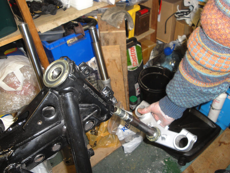
Dismantling front wheel, forks and the steering head (yokes and bearings) was really straightforward - no explosions involved. I supported the bike with a plank under the sump, resting on bricks so the front wheel was just clear of the ground. There were no stuck or rounded bolts to deal with, and no obvious corrosion - at least, not at first.

The steering head is supported by taper roller bearings. The top bearing (marked Koyo 32005JR) drops onto its tapered seat and is clamped in place by a threaded collar. 

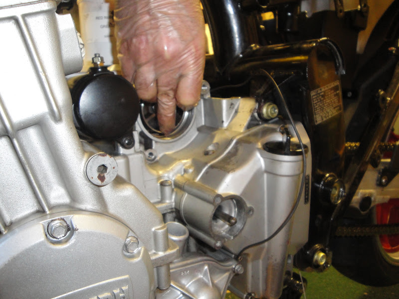
Bottom steering head bearing
before waxy old grease
was cleaned out ... 
... and again after cleaning.
Mucky residue visible in the pan.
 The bottom bearing is an interference fit on the steering stem, flush with the bottom yoke. Both were greased but it had a waxy consistency - probably as old as the bike. 22 years old, that is: the underside of the bottom yoke is marked 20th of December 1990. So I flushed it out with a paraffin in my trusty stainless pan and a toothbrush.


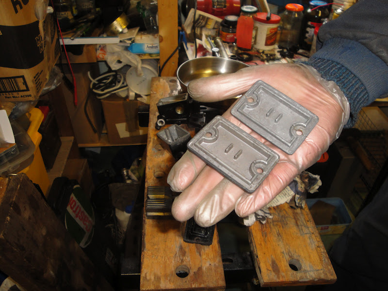
The steering stem has a strange rectangular slot at its midpoint. I've no idea what this is for. My best guess is that it is something to do with the manufacturing process, maybe for clamping for insertion into the bottom yoke.
 I filled the cleaned bearings with grease by wiping fresh grease onto the outer surface of the rollers, spinning the bearing to carry some of the grease inside, then wiping on some more and repeating the process until the rollers were all rotating out in a properly lubricated condition. The same technique works equally well for top and bottom bearings, it's just a bit more cumbersome with the bottom one.


The top bearing just drops into its tapered seat in the top of the steering head. The seat was in great condition. Hooray! The bottom seat was also in fab condition. There is a rubber dust seal beneath the bottom bearing - it did a good job of keeping the grease in place so that's probably why. The steering stem passes through the steering head and top bearing, and is then retained in place by a threaded aluminium collar.

 The collar on these early bikes is intended to be turned by hand to a point where vertical movement in the bearings is just eliminated, and no more. It is a judgement, this, made complicated by the stickiness of the grease. After two or three tightenings and slackening off, I was happy with the level of tension I'd put into them and the left-to-right movement of the steering action. So I lightly torqued up the M6 pinch bolt to the specified level.
 The top yoke holds the ignition switch/lock assembly. It is bolted in place with security bolts so cannot be removed without awkward drilling. Consequently, the top yoke has to be installed twisted about 80 degrees from straight ahead so the lock misses the frame bracket with which it will later engage. It fooled me at first. The top yoke is ultimately torqued up when the forks and wheels are installed and checked for alignment.


Next step, strip clean and inspect the forks. 

Wednesday, June 27, 2012

Rear brake and gear change foot controls

The rear brake and gear change levers are operated in a similar way. The levers both pivot on a shaft that extends from the rider's footrest. The shaft then passes through a substantial alloy casting (previously restored) and is bolted up with a M10 button-headed allen bolt. 
Brake lever, footrest incorporating pivot
lug, and alloy casting. The bottle is thread
lock solution, to be applied to the footrest
retaining bolt. 

The levers have a lug extending from beneath the pivot point and to which is attached a linkage rod to the rear master cylinder, in the case of the brake lever, or a short secondary lever on the splined gear change shaft, in the case of the gear lever. Both levers benefit from the protection and lubricated action of a special bush (phosphor bronze?). How nice, once again, to see evidence of a design team who cared about the long-term viability of the machines they were creating


The brake lever is attached to its operating rod by a simple clevis pin. I fitted a stainless washer and R-clip to the clevis pin the clevis pin, along with plenty of grease.

The gear lever is attached it operating rod via a rose joint, with another rose jointed coupling for this little rod on the gear change shaft. They get a lot of action in a harsh environment - down low on the bike in the wet. I carefully forced as much grease as I could into the joint using a small screwdriver, holding the joint to make a gap between its internal ball and external housing, and rotating it frequently to spread the grease around. Result: beautiful smooth action.


The footrests were loose when I got the bike and the bearings dry. It isn't easy to do them up off the bike - impossible with the alloy plates installed. It's no small matter to lubricate them either so again plenty of grease here. I used threadlock compound to help keep them in place. In any case, I found it was a bit of a challenge to torque up the M10 retaining bolt off the bike. After trying a few different ways to hold the alloy casting, I found I could clamp it at an angle in my notWorkmate.


After all that, bolting in place with two M8s, one into a captive nut  and the lower one into a separate locking nut, means I have a place to put my feet and, though I say so myself, a great gearchange action.


Wednesday, June 20, 2012

Pump, alternator and tidying up the front of the engine.W

Having refitted the engine covers, I was ready to install the alternator and water pump. The shiny state of these components showed up the rather tatty state of the front of the engine at the same time. So, despite my claims that I would focus on adjusting and lubricating from now on, I couldn't leave it.

I've become fond of using red rubber grease every time rubber components are involved. In the case of the alternator, it was handy for keeping four rubber cush drive blocks in place. The drive works on four vanes on a sort of sprocket that is bolted to the alternator shaft. The cush drive blocks fit between these vanes and the drive, visible as a circular aperture behind my hand in the photo below. The blocks kept falling out of place before I could locate the alternator vanes. I found that sticky red rubber grease did a great job of keeping them put plus, I'm hoping, giving them an easier time in their shock absorbing role.


 Turning attention to the cooling system, I got new gaskets for the two hose spigots that the water hoses connect to. The curved one behind the cylinder block is for returning hot water to the pump. The small straight pipe near the left-hand sparkplug tunnel is for the cold water feed to the engine from the radiator.


Water pipe test fitted to the front of the engine, showing
slightly tatty 'before' state 
Front of engine after washing down with white
spirit to remove grease and road tar, then spraying
with VHT silver and clear laquor
I added stainless washers above and below the standard fibre washer that dampens engine vibration from damaging the water feed pipe from the pump to the bottom of the radiator.  The fibre washer I removed was pretty mashed up so I thought I'd give it an easier time this way. New copper washer on the M6 cylinder drain bolt. 


Comparing the left-hand side of the engine before (left) and after (right) my work. I guess it all amounts to going from 'tired' to 'as new' condition. Was it all worth it?

To me, yes, it is.

A clutch of small problems

I found the hydraulic system for the clutch to be heavily contaminated with a strange orange brown gunge. I suppose it is some kind of emulsion of hydraulic fluid and water because the fluid is hygroscopic (absorbs water). Whatever the cause, the effect was horrible and evident throughout, coating the inner surface of the slave cylinder, spring and piston:


 ... and the master cylinder reservoir and piston. The master cylinder cap and rubber seal were coated in a crust of corrosion and a jelly-like substance. The jelly was awkward to remove - I used a combination of a flat bladed screwdriver for scooping out the big bits and kitchen towel soaked in clean hydraulic fluid.


Two reservoir caps are pictured because I cleaned up and lubricated the front brake master cylinder at the same time. I rubbed back the reservoir caps with a plastic alternative to wire wool made by the Scotch company and wiped them down with white spirit. After it has dried off completely, I treated the caps to a coat of Hammerite direct-to-galvanized black paint. 


The master cylinder pistons for clutch and front brake are rather different. The clutch piston return spring is heavier than the one of the brake. The piston for the clutch is operated via a short rod that fits into a recess in the end of the piston and a small boss in the clutch lever. The piston for the brake is acted on directly by the front brake lever. 
Master cylinder pistons for clutch (pictured left) and front brake (pictured to the right)
The pictures below show the cleaned and reconstructed clutch master cylinder. The piston is retained by a washer and an internal circlip. It was a bit awkward replacing the circlip for the clutch - very awkward for the brake because the end of the piston is bigger so there was less room in the bore for my circlip pliers. 

I'd bought a complete set of stainless steel Hel hydraulic lines for the bike. I'd asked for later spec lengths for front brake and clutch to allow for the fitting of higher handlebars, should I decide to go for a more relaxed riding position at some point.

I'd wondered how much heavier the braided lines would be than the standard rubber hoses - so I put them in an old kitched scales to find out. I was amazed to see that the Hel clutch line was actually a lot lighter than the rubber hose, despite being longer. Well well.

 The clutch slave cylinder was treated to a coat of high temperature paint and the piston, return spring and hydraulic seal all carefully cleaned off ready for refitting.


The clutch lever itself had worn considerably at the pivot point. The alloy leaver has a bush pressed in to its pivot point cope with the mechanical torsion of operation. It had both worn and apparently spread into the alloy of the lever body. I've got a pattern replacement on order but would like to see if I can refurbish this one by sourcing and bronze or brass bush, drilling out the pivot point and pressing in a replacement.