Saturday, November 10, 2012

Failed tank liner

I have been having intermittent problems with fuel starvation. The effect of this has been running on two cylinders, cutting out, then restarting after a few minutes at the side of the road. I know it is a fuel starvation problem because the bike would run on either cylinders 1 and 2 or 3 and 4: both combinations are served by both coils so coil failure could be responsible. I have had trouble with one or other of the petrol pipes doubling over and cutting off the supply to the left or right pair of carbs. Also, I have fitted two clear fuel filters into the petrol pipes and so I could see them empty of fuel when the bike has come to a stop, and then gradually refill. I figured that flakes of the liner were probably wrapping themselves around the filter that is integral with the petrol tap, thereby restricting the flow of petrol through to the carburettors. I had previously had a go at removing all the loose liner from my petrol tank, including fishing in it with a spring-loaded grabber tool and then draining it entirely. I managed to get a lot out and thought the remainder was sound. However, the return of the starvation problem suggested otherwise. I was pretty sure that once again the failed liner was at the root of the problem so I decided to try getting some more of it out.

Grabber tool having picked up a load of tank liner
I used my grabber tool again and soon found it wasn't hard to fish out large flakes of the liner that had come loose inside the tank and was floating about in the petrol supply.

Failed liner 1
In the photo above, you can see the size of these flakes in relation to the petrol filler.

DSC05709
So after about 30 minutes of work, I managed to get a considerable amount more of the failed liner out of the tank. I'm pretty sure there aren't any other large flakes there right now but I'm equally sure more will come looses and foul the fuel outlet once again.

Friday, November 2, 2012

A Trip to Trevor

I took advantage of the slightly less appalling weather today to visit Sprint Manufacturing at Upton Lovell in Wiltshire. Although the air temperature is pretty low now, with the damp taking effect, it was a nice run out. The sun lit up the gold and russets in the trees along with the remaining green leaves along the way.
Trevor is the Chief at Sprint Manufacturing. His premises are well off the beaten track, business being overwhelmingly made up of web and telephone mail order. It's not a big trip for me to get there in person though and a nice ride to boot. I found him in the midst of applying a gel coat to a hugger he was making for an Australian customer. A top quality job, needless to say. He told me the classic fairings side of his business are popular in Japan, to the tune of an order a week in the summer.
Anyway, Trevor has helped me out on many occasions, supplying good advice, good parts and good humour at all the right times. Several times on previous visits, I'd said I'd bring my 1200 for him to see when it was finished. I'm sure he's seen dozens of the things before so it was more of an excuse for me to get out and seek approval from the master than a case of me showing him something new.
So I set the bike up on its centre stand, started the motor and asked him what he thought. Here he is, focusing his full force of his mystical powers to commune with the inner workings of a T300 in action:

A visit to Sprint Manufacturing 2

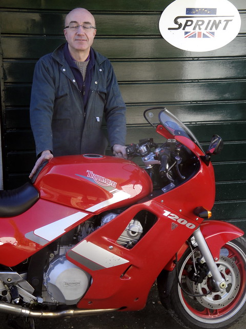
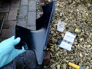
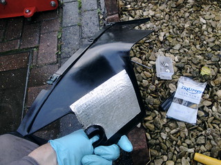
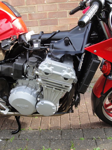
He was impressed with the quietness of the motor compared with others of its ilk. He told me the early die-cast cases (with access hatch for sprag and alternator drive gears) are noticeably quieter than the later Cosworth pressure sandcast cases. I forgot to say that the 1991 bikes have foam-lined fairing panels too, dampening the sound further. And the result. Well, was it in doubt? I think it met with his approval.

A visit to Sprint Manufacturing 1

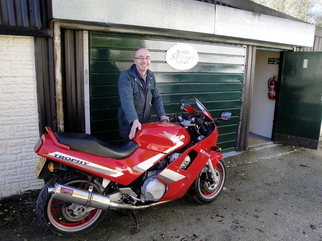
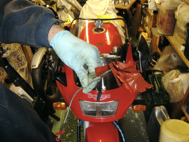
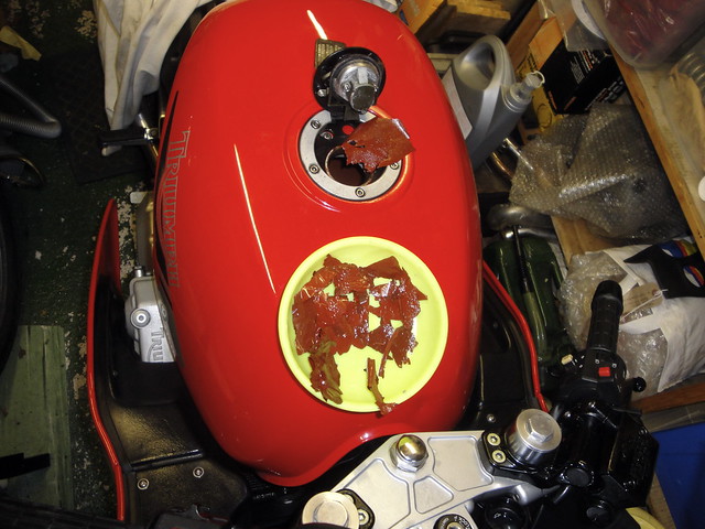
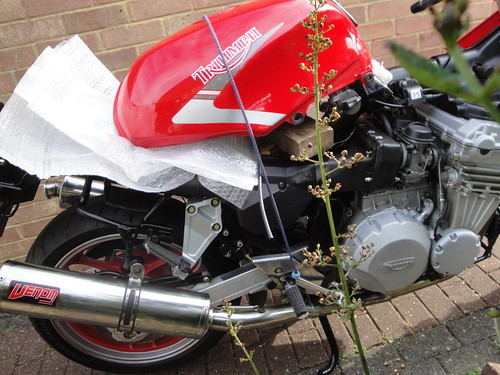
The bike had run beautifully all the way there. Irritatingly, I had more fueling problems on the way home. Maybe the bike was sad to have had to leave the cosseting world of Sprint. But seriously, I think I've got four issues to deal with, two of which are probably self-inflicted. 1/ The loose sheets of liner are wrapping themselves around the fuel tap's integral filter 2/ the fuel tap prime position isn't passing any fuel, 3/ the angle of the extended fuel pipes and filters I fitted seems to be causing at least one hose to fold. 4/ The extended pipes are also putting pressure on the vacuum pipe to the rear of the fuel tap. So I shall address all these issues before taking her out on the road again.

Monday, October 22, 2012

Fuel cap

I wanted to make sure my fuel cap was functioning properly. I have had some problems with the breather on the identical item on my 900. It has occasionally failed to admit sufficient air into the tank to allow fuel to exit, especially after a period of high speed running.

The cap is an aircraft-style flush filler cap, operated with a key in spring-loaded mechanism. The key hole is itself hidden under a sprung cover. This cover was loose, not snapping shut, and the key was not centering after the cap was pushed home. Not a big deal but I thought I'd see if I could clean out the components and restore some snap to the action.
The main components of the cap are visible above, including a lid with rotating centre that is hinged to an alloy ring; a retaining tang which is drawn back by the two pegs on the rotating centre; a small spring which forces the tang out to retain the lid by clipping under the forward edge of the tank's filler hole; the main fuel seal which is held against the tank's fuel filler hole by four small springs; a tang retaining cover, and steel retaining disc and two screws which clamp the tang holder and seal in place.

DSC05481 DSC05482
The fuel tank breather is a small air passage that runs from a little hole in the tang retaining cover, through a casting that contains the lock barrel, and through a pair of diaphragms to another little hole next to the hinge. The tank emits a rather attractive humming, whistling noise when in the sun or cooling down after a run. The noise is made by fuel vapor escaping, or air being drawn through these diaphragms.

The little holes are indicated by the tip of a screwdriver in the pictures above. The left-hand picture above shows the cap without the main fuel seal in place. The four small springs visible around the rotating body apply pressure to the main fuel seal to ensure it works effectively. The right-hand picture shows the cap reassembled.

DSC05521 DSC05523

The cap assembly is retained by four screws into the top of the tank. One is under the lid, preventing the cap from being removed without unlocking it first, the other three are allen-headed screws that pass through the periphery of the hinge ring. Two of the allen-headed screws are just decorative. A rubber dust and dirt seal fits into the top of the tank first, followed by the cap hinge ring.

One retaining screw is under the cap

I cleaned off all the corrosion from the components and lubricated the rubber seal with rubber grease, and the spring-loaded tang with copper grease. I replaced the inner screws with stainless items. Job done.

Sunday, October 21, 2012

Radiator and Oil Cooler cowling

I hadn't got around to fitting the final part of my fairing. It is a plastic cowling or duct that fits between the radiator and oil cooler, behind the front mudguard. The air is getting cooler now we are firmly into the autumn months. I thought it would be good to try it when the heat is easiest for the cooling system to deal with.

The cowling itself is made from a different type of plastic compared to the fairing itself. It is more rigid and, I hope, heat resistant. It has an aluminium heat shield patch on the rear, corresponding to a fitted position just in front of the exhausts.
T312 cowl - front T312 cowl - rear

It is retained by eight screws that wind into spring clips and two M6 bolts that also secure the top of the oil cooler.
Installing cowl Cowl installed

I'd bought some replacement clips from Lings as part of a larger order. I decided to use stainless self-tapping replacements for the original black screws and dabbed Waxoyl on the clips to keep corrosion at bay. The M6 bolts were also replace with stainless alternatives: in this case, button-head screws with stainless penny washers.
Cowl viewed over mudguard
One thought I had was that the cowling could improve cooling by forming a dam of cool air when the bike is in motion, rather than the cool air 'escaping' through the gap between the radiator and the cooler. In slow traffic, it would be of limited value or worse, with the exhaust being unable to radiator or convect heat back out to the front of the machine. Then again, when the fan engages, it could benefit from the fact that only cool air could be drawn through the radiator rather than hot air spilling back out from the exhausts.

A short ride tonight didn't really prove anything other than that the cooling system is behaving predictably and the fan came on after idling stationary for a while. Fair enough.
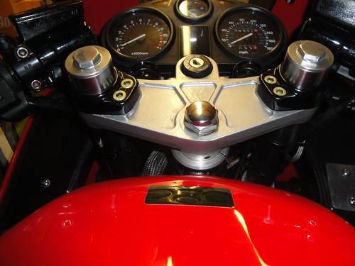
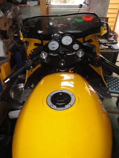
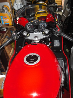
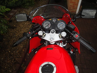
Friday, October 19, 2012

Lowering front suspension

After riding my renovated Hinckley Triumph for a few weeks now, I'm forming a better impression of how it behaves on the road in various conditions: wet, dry, dual carriage ways, A-road and B-roads. Compared to my 900, the 1200 Trophy provides a much smoother and roomier ride. The power is delivered with less vibration, the bars are more upright, and the suspension rides over ripples and bumps more evenly.

DSC05653
The power builds more slowly at first but gets exponentially stronger with a noticeable woosh between 3500 and 4000. At 6000, the engine note takes on a harsher edge, vibration intrudes and the whole world seems to go into reverse. The bike is supremely stable at all times. However, the steering is noticeably slow compared to my Daytona. The effect is a swoopy bend swinging experience that adds to the sense of smoothness. I could wax lyrical Jaguar style: grace, pace and space.

DSC05654

I thought I'd experiment with the degree of fork pull-through. The effect of more pull-through would be to marginally change a number of things that can influence the steering. It will reduce the front ride height, lower the center of gravity, steepen the steering angle, reduce the trail, and I'm pitch me further forward an inch. This should make the bike respond more quickly to steering input. Triumph list a range of pull-through settings for different T300 models. They are measured from flush with the top yoke face to the top of the steel fork tube, just below the fork top nut:
  • Trophy, Trident & Sprint to      VIN 29155: 25mm
  • Trophy, Trident & Sprint from VIN 29156: 20mm
  • Daytona & Speed Triple to       VIN 29155: 28mm
  • Daytona & Speed Triple from  VIN 29156: 0mm (flush)
I had already allowed an additional 10mm (total 35mm) of pull-through to compensate for the fact that I'd installed 20% stiffer springs. I'd calculated that the difference in spring rates would mean so doing would maintain approximately the standard ride height. So this time, I pulled the forks through an additional 14mm (24mm), or just under and inch in total above the base figure.

Extra24mm

Although as I say such a change will result in a very small difference in each of the relevant parameters, the nett effect can be noticeable. Would it be for me?

Stanchions proud of handlebar mountings


The answer is yes. I'm afraid it is still a case of impressions rather than hard data but I'd say my Trophy 1200 feels very very similar to the Daytona 900 like this. There is no hint of delay now between input at the steering and effect on the machine. Dropping the front by an inch means the seat is about half an inch lower. Although it means my hands are an inch lower, the angle of hands to forearms, shoulders etc. is unchanged. The ride feels that bit more direct.

Some issues to be aware of:
  1. it is much harder to get the bike onto its center stand now. Far harder. Herniating, I shouldn't wonder.
  2. the belly pan is an inch closer to the road - sleeping policemen must be treated with caution, bumping up curbs is totally out (a good thing not to be tempted to do). 
  3. the steering is more sensitive to running over cats eyes now. 
 I can live with all of these things for now.

SitsLower

Monday, October 15, 2012

Mirror alternatives

The original mirrors on the faired Hinckley Triumphs (Trophy 1200 and 900, Daytona 1000 and 750) were all the same: round-headed items on short stalks that are attached to the fairing subframe with two M6 studs. They also serve as the main attachment point for the top fairing.

 They are good quality items that are basically vibration-free - but don't show the rider very much more than an attractive view of the elbows. At least, that's what they show unless the rider makes a conscious effort to tuck their elbows in. The stalks are retained in the mirror heads by nuts but can't be dismantled to do much about the length.


My bike came fitted with some alternatives that later became standard on the Trophy models (1993 I think). These mirrors are about the same height but have a wider, oblong profile so extending the view laterally by about an inch. Ideally, they'd be mounted on stalks that are around an inch wider again. The stalks are moulded extensions of the mirror body so can't be extended.

So I've been keeping an eye open for other possible alternatives. I saw these on ebay being mentioned on the Yahoo Triumph Trophy group:


They have adjustable M6 studs so would work and have integrated indicators. They look as though they could be dismantled and the stalks extended. Might give it a try some time.

Thursday, October 11, 2012

Daytona vs. Trophy cockpit

I thought it would be interesting to do a side-by-side comparison of the layout of the '94 Daytona and '91 Trophy cockpits. So I have tried to photograph the two of the so the angle and distance of the camera was pretty much the same. I haven't quite got it right, but it's close.
The key points of reference for comparison are the ignition lock for height and fork centres for width. The bars are also the same length and have the same pull-back angle so help to show how the two variants of the Hinckley T300 project relate to one another. Bars can be changed though so there is potential variability. In fact, the height of the bars is one of the main things that define what they are like to ride for pitching the rider's weight forward and more behind the screen, or backward/upright and more in the air.

DSC05648 Trophy cockpit
1994 Daytona Cockpit 1991 Trophy Cockpit
The Daytona fairing is considerably wider than that of the Trophy at the top of the screen - maybe 30% wider - though the width is similar at the level of the top yoke. In the pictures above, this is easiest to see by comparing where the line of the fairings crosses the switch gear left and right.

The screens are both standard fitments for their years. The Daytona screen is marginally lower than the Trophy. The Daytona bars are mounted beneath the top yoke, the Trophy's are above, a difference of about 2 inches. The effect of bar and screen height when riding is that the Daytona keeps more of the wind off but directs windblast into the middle of my helmet. I'm 6'4'' though so it's conceivable a shorter rider would be out of the wind altogether ... if they could reach across the long tank to get hold of them in the first place!

I have found when riding the Trophy that my shoulders are just in the wind but the wind blast off of the screen hits me around the top of the chest. My helmet is in clear air so it's much quieter because there is less buffeting and the volume of wind hitting the helmet is lower.

The Daytona cockpit isn't quite standard - I made my own carbon fibre clock bracket to the same dimensions as the original and fitted a time clock just above the speedo.

Tuesday, October 9, 2012

Shake down

My first longer run took me out of town through Wiltshire up to Salisbury Plane. I noticed a small autoelectrical trader on the way with a famous sign from Triumph's past:

DSC05590

Joe Lucas: Home Before Dark.

I enjoyed the surging smooth feeling of the 1200 engine, the suspension feeling pretty plush though on this trip harder at the front than at the back. I hadn't yet made any adjustments to the rear shock. Front end felt pretty good. I was still very much of a mind to focus on the feel of the bike, gently building up speed demands on handling as I went. A mindful ride. Very enjoyable. I just kept going until the sun went down. There are times when riding just feels like the right thing to be doing. It was a fine if rather cold day. It was one of those perfect riding days. Sunset on Salisbury Plane 2 
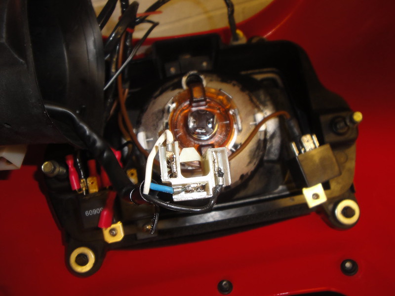
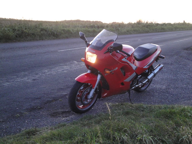
Even after all the tinkering to get the most I can out of the dip beam on my headlight, it isn't great. It is just adequate. But adequate does mean I have no need to worry about the dark any more.


Sunset on Salisbury Plane 1 

Running on two cylinders

When I started my Trophy 12 for its MOT, I was disappointed to find that she dropped onto two cylinders after a couple of minutes. She was running beautifully the night before. Lovely even beat. What could have happened? I had my appointment booked though and thought it might be some muck in the carbs or maybe something that would clear as the engine warmed up. 

Not so. Warming up didn't make any difference. Maybe one of my coils had failed. Each coil controls a pair of cylinders so it was possible. However, the two cylinders that were not running were numbers 3 and 4. The pipes on these cylinders were cold. One coil runs cylinders 1 and 4, the other runs cylinders 2 and 3: it could not be a coil/ignition problem. So attention turned to the fuelling side of the equation.
 
I had thought that the two fuel lines were to ensure an adequate feed of fuel at high speed, and that they fed a common gallery for all four carburettors. This was an assumption. Looking at the carbs, I now see that one fuel pipe feeds cylinders 1 and 2, the other feeds cylinders 3 and 4.

To cut a long story short, I found that I had pinched one of the two fuel lines that runs from the fuel tap to the carbs. The previous night, I had not bolted the fuel tank in place. Of course, I wouldn't take to the streets with the fuel tank insecure so I had fastened it down the following morning.

To remedy the problem, I took a close look at the routing of the fuel lines. One of them pushes on to the rear of the tap, the other pushes on from the right-hand side. I had used much thicker fuel lines to replace the hardened originals. This meant that they need more room to physically fit in tight spaces and require bends with a wider radius. I had inadvertently routed the bike's wiring loom along the main frame tube exactly where the rear fuel line would need to turn when the tank is fastened. So I solved the problem by pulling the wiring loom further around the frame tube and securing it with an additional cable tie. That gave the fuel line sufficient clearance to bend around the frame tube without too much difficulty.

The result: all working beautifully. The engine's creamy smooth thrust was restored, allowing me to start enjoying the bike in the next few days. It was still very much in shake-down mode for fault finding and rectification. A great feeling.


DSC05571

Thursday, October 4, 2012

How dim - H4 pin wiring

The headlight on the early Trophys has a poor reputation for the strength of its low beam. I decided to see if I could improve it in two ways. First and most importantly, to ensure there was a good power to the bulb. Secondly, to fit a xenon bulb because the light they produce is closer to daylight colour than standard halogen bulbs.
A good power feed means making sure the wiring delivers a real 12 volts at the bulb terminals. It also means having a reliable earth. The early Trophy has a single halogen H4 headlight that takes its power via the right-hand switch cluster. Daytonas have twin H4s that take their power via relays from a separate feed. There is a chance that the circuitous route taken by the power might mean a voltage drop. I checked the voltage at the terminals and it was around 10.5 volts whereas the battery was showing a clear 12.4 volts across its terminals. A bit of a drop is normal - this is too much so I was sure I needed to do something about it.
Headlight block connector on main loom, with separate heavy guage switched live
A close look at the loom wiring to the headlight block connector suggested to me that the wire was a bit on the thin side. The picture above shows four wires in the connector: brown-white is the feed for the side light, red-black for the high-beam, red-yellow for low beam, and black-yellow for earth. The thinner the wire, the higher the resistance and hence the higher the voltage drop. The comparison of the separate feed (white wire) made this difference particularly noticeable.
The headlight connects to the loom via a small harness. Rather strangely, in my view, the colour coding in this little harness is completely different to the scheme for the main loom. Its four wires were blue for earth, yellow for side light, black for high beam and white for low beam. On the plus side, the wires themselves were quite a bit thicker than those in the main loom.
DSC05334
Having loosely fitted the cockpit fairing, I could see there was sufficient space to fit some relays in the same way as the Daytona headlight. I could make sure the horns also benefitted from max voltage at the same time by feeding them from a relay. The horns work by earthing through the horn switch in the left-hand switch gear. I'd fitted car horns which draw more current than the original bike horns, for the benefit of being REALLY LOUD. I discovered that they worked perfectly well individually, but would not produce a note when both were wired on. I think they were giving the horn switch a very hard time. I could use the heavy gauge feed for all three relays. So that's what I did.
Headlight wires extracted from H4 connector
I extracted the terminals from the H4 and loom block connectors and cut the wires ready for splicing in new wires to lead from the loom to the relay switch terminals, and from the relay power feed back to the headlight. I had some wires of near the right colours in my spares box.
terminals soldered to new wires Headlight wires after shrink wrapping
After soldering and insulating with heat-shrinking tube, I coated the terminals in petroleum jelly and refitted them into the block connector.
Coating electrical connectors in petroleum jelly Reassembling headlight block connector
Making up the power feed and earth was straight forward, using new insulated female crimp spade connectors. I tinned the ends of the wires first to help seal out moisture and get a firmer connection with the wire crimpers. For the power feed, I used thick brown wire with a male bullet on one end to couple with the white feed, and soldered in three branches to it as feeds for the three relays (horn, high beam and low beam). For the earth, I made up a similar wire with two branches. I made up a new frame earth because I wasn't sure the gauge of the earth in the block connector was adequate for the load. The picture below shows how it all came together:
Block connector with feed and earth wires
At my MOT, the tester pointed out that my dip beam was very yellow compared to the main beam. I'd installed a xenon H4 bulb, which should have a blue tinge to it so something wasn't right. He suggested I check to make sure that the bulb was earthed on the correct pin. The rear of an H4 bulb has its three terminals (high-beam feed, low-beam feed, and earth) arranged in a horse shoe. The earth should be on the left terminal, low-beam at the top terminal, and high-beam terminal on the right. Sure enough, when I checked I'd messed up the earth position in the H4 connector. Still, I knew my way around the wiring by then so released the black and white wires, swapped them over and all was good.
DSC05561
Relays in place in the cockpit fairing, wiring ready for coupling to main harness


Tuesday, October 2, 2012

Off to the MOT

For readers outside of the UK, the MOT is a mandatory annual test that all motor vehicles must pass if they are to be used on public roads. MOT stands for Ministry Of Transport. My bike had been off the road and without the need on an MOT for two years so, before I could allow her to roam free once more on British roads, I had to get her to my wonderful local MOT tester.

Although of course I had repaired, refurbished and/or refitted pretty well all of the running gear, I rechecked everything I could think of and road the bike backwards and forwards on my little drive. So the night before my MOT appointment, I ran the bike through at set of checks I've got used to performing in advance of the annual exam. I couldn't find any obvious problems but knew the headlight wasn't working as well as it should. I'd spotted that the wiring from the main loom was thin compared to the little harness that connects from the loom to the H4 headlight bulb.

The feel of the motor was just superb in these little tests. I had expected it to be running unevenly because I had reset the carburettors in cleaning them and so thought they'd be out of balance. As it happens, my attempt to get the carbs somewhere near by visually adjusting the DV carb throttle plates so they were all opening at about the same time with the throttle. The whole feel of the bike was just fantastic. I'm sorry that this is such an emotional and uninformative term to use. It's just that, for me, it was everything and more than I had hoped for. It's true, the gear selection felt a bit harsh - a real clunk - but I was used to this from my Daytona 900 when that motor was younger. The sense I had, just allowing the motor to pull the bike along at walking pace, was that it was willing and turbine smooth. No juddering, hesitation or shaking: just an even solid thrust.
This is how she sounded and ran at that particular moment:

You will see that the digital oil pressure and oil temperature gauges appear to be working correctly. They are powered from a spare coil positive wire courtesy of the fact that the loom was common right across the whole range in 1991 (the four-cylinder engines need two, the three-cylinder engines use three coils). So when I change the engine kill switch from off to on, the gauges are powered up and flash all segments of their LED display in the process. The then start to read oil temperature (right-hand gauge) and oil pressure (left-hand gauge). I discovered that the lowest temperature that the temp gauge can show is 25 degrees centigrade. So when it shows 25, it doesn't mean anything at all. The fact that it starts up in the 40's in this video is because the motor was warm from the first startup. The striking thing for me about the oil pressure is how high it reads when the engine is cold. Cold oil must be a lot thicker than oil at the correct operating temperature. I shall write more on this in a later posting. I had decided not to refit the fairing panels until I was confident that everything that would be hidden by them was working properly and leak-free. Rear fairing panels refitted, front panels off for shakedown test

Setting off for the MOT next day threw up my first problem: she was only running on two. I couldn't believe it after the 'pre-flight checks' the previous evening. Oh well. I had an appointment to keep so set up in lumpy fashion for the test. 

I have got to know the MOT tester at my local bike shop over several years. I never ask for any special consideration, though probably get it. I like the guy very much because he really knows what he is doing, is friendly and considerate and won't cut corners on the test. He found two problems with the bike. One was not unexpected: the headlight beam was out of adjustment. The other was that the electrical cables from the right-hand switch gear were catching as the handlebars turned from lock to lock. He allowed me to adjust the former and solve the latter with a cable tie. Everything else was in order and he complemented me on the cleanliness of the underside of my engine.
What a guy!
He said he thought there was a mistake in the wiring of my H4 bulb because the dip beam was very yellow in colour. He said this can happen if the wrong H4 terminal is earthed. So that needs checking. The dip beam on early Trophys is notoriously poor anyway and I had decided I'd address the fact that the main loom appears to have under sized feeds for the headlight anyway.
The nett result is one 1991 Triumph Trophy 1200 back on the road in Britain, 21 years after it first left the Hinckley factory. A great result for me.
DSC05539
After the MOT Just back from the MOT test station 

We exchanged some thoughts on the rough running engine formed a plan to sort it out.  


Saturday, September 29, 2012

Three AM is a wonderful time for insight


I woke up at 3am, lots of things running through my mind. Mainly work stuff. Then it just came to me that I hadn't actually checked to make sure I had the correct pair of wires on the low-tension side of the coils.

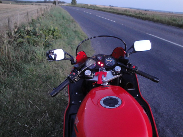
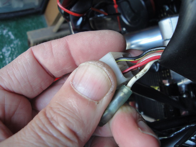
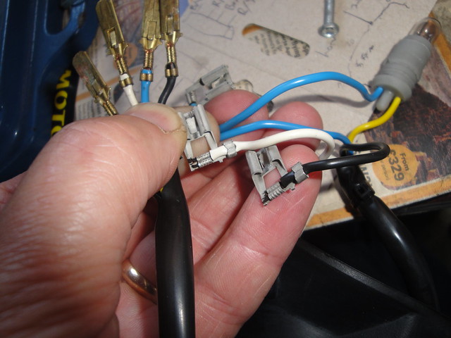
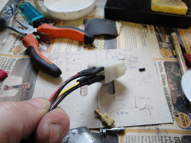
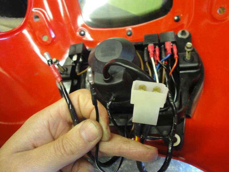
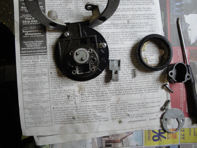
Strangely, the factory and Haynes manuals had no clue about which pair belong where. I just thought, what the hell, switch them around after work and give it a go. And go she did! Just like that. You could have knocked me down with a feather.

So the engine wouldn't run before because the timing was exactly 180 degrees out (i.e. approaching BDC instead of TDC) on all cylinders. The coils are wired in two pairs to fire every 360 degrees, which is towards compression on one cylinder of the pair at the same time as the other is on its exhaust stroke. Instead of that, I'd had it sparking towards the start of the exhaust stroke on one cylinder and the end of the induction stroke on the other.

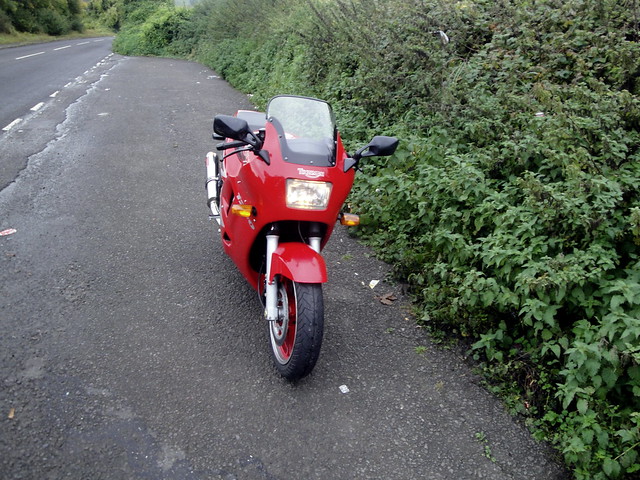
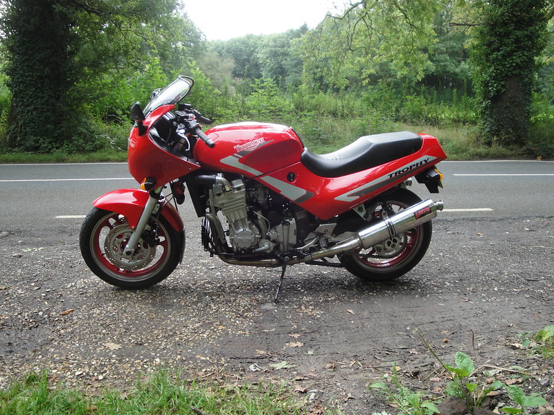
It isn't quite the end of the rebuild. MOT and tax next, plus some shake-down rides without the fairing lowers so I can see and sort any problems if and when they develop.

Purrring. Great.

The best LeT plans of mice and men ...


So with the carbs in place and fuel supply sorted courtesy of my piggy-back tank arrangement, the great post-rebuild start-up moment had arrived.

Piggy-back petrol tank Piggy-back petrol tank 2

At least that was the plan. The reality was a lot of ny-ny-nya-nya-nya-nya-nyaaa. Nothing. ny-ny-nya-BANG-ny. BANG. Exciting, certainly. Rewarding, no.

I pulled out the spark plugs to make sure they hadn't fouled with the Redex I had put down the bores and intakes. Result: sparkers looked great when they came out. Refitting just gave more of the BANG same ny-ny-nya. BANG.

Friday, September 28, 2012

Carburettors and fuelling

I was confident that my Trophy's misfire was due to an ignition fault. However, there was a chance it could be related to fuelling. My general thought was to do the best I could to get all the engine systems in tip-top condition, from the starter motor through airbox and carbs to spark plugs. The age of the machine (approaching 21 years) probably meant there'd be plenty of muck in the carbs and that the floats would benefit from attention.

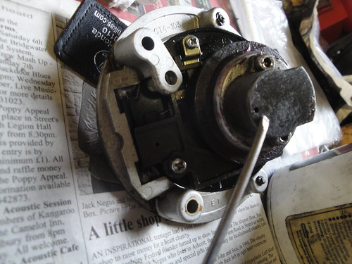
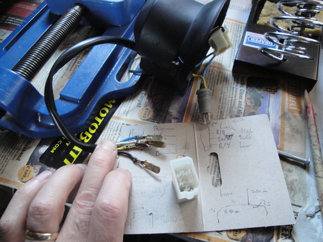
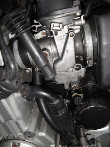
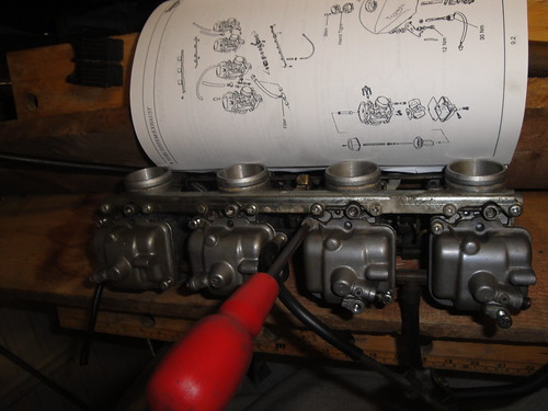
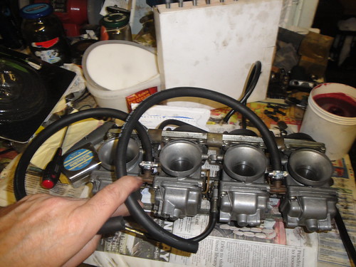
The 125BHP 1991 Trophys are fitted with a bank of four Mikuni BST36 flat slide constant velocity carburettors with the serial number 1240010T0301.

Mikuni BST36 flat slide CV carburettors

  • Cylinders one and four both have SE60-3 jet needles and 112.5 mains.
  • Cylinders two and three both have SE77-3 jet needles and 117.5 mains.
  • Needle jets (0.8) and pilot jets (40.0) are common to all four carbs.
There was evidence of fuel seepage, a golden-brown glaze, on the edges of the float bowls and staining underneath, and of course plenty of grime everywhere in the induction area.

Induction rubbers on strip down

The carbs strip down without much drama, as long as the bank is firmly supported so you can get a good grip on a Philips #2 screwdriver to release the float bowls. I found that corrosion had crept between the float bowl seals and the carb bodies throughout. I cleaned it off with a blunt screwdriver and WD40. The float levels needed minor adjustment only (a millimeter or two). There was a fine rust-brown deposit in all the bowls.

DSC01265 Corrosion in float bowls had crept under rubber seals, causing leakage

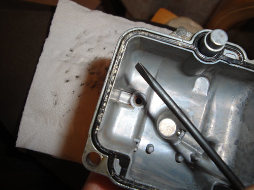
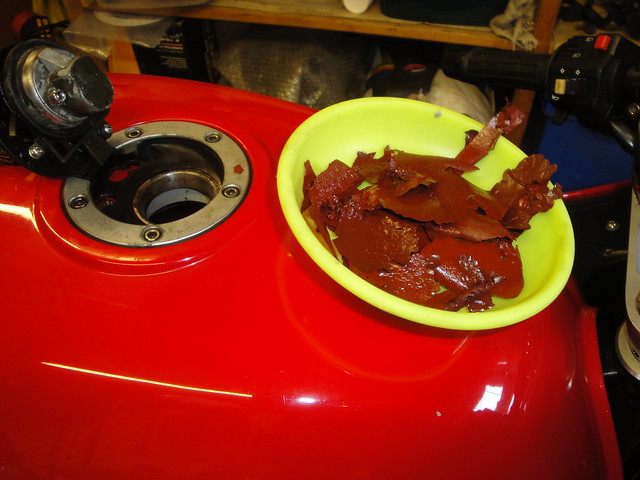
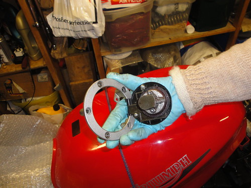
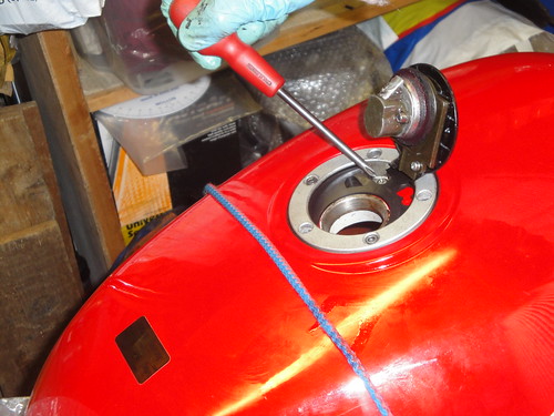
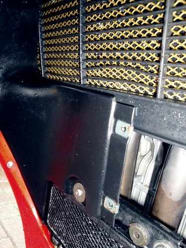
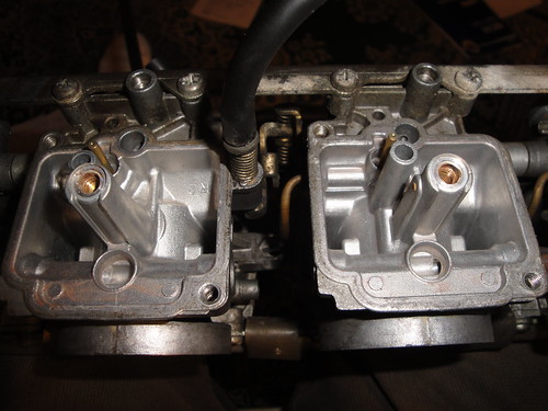
There are two plastic mesh filters fitted into the fuel line spigots as standard. These showed no evidence of contamination. I think the stuff that had collected in the float bowls was too fine to be stopped by the plastic filters. In fact, the petrol tap also incorporates a fine plastic mesh filter - still too coarse to have kept this silt from the carb bodies. An old toothbrush and carb cleaner sorted this out in a thoroughly satisfactory manner. The bank of four, upside down and ready for some serious attention Shiney

Original fuel lines had hardened 
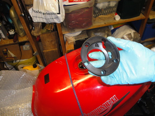
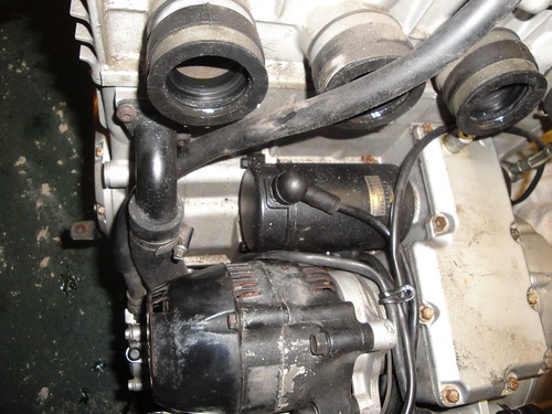
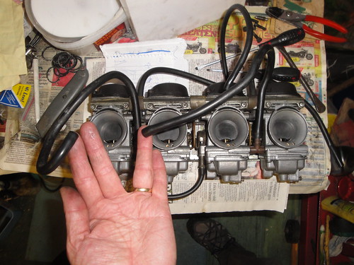
The carbs are fed by two fuel lines, each being 7mm bore preshaped plastic pipes. Both had hardened over time - quite understandably - making me think it would be unsafe to reuse them. I bought a meter of 7.6mm bore fuel injection hose and some new hose clips to replace them, along with two inline fuel filters with paper elements.

7.6mm fuel injection hoses New fuel line in place

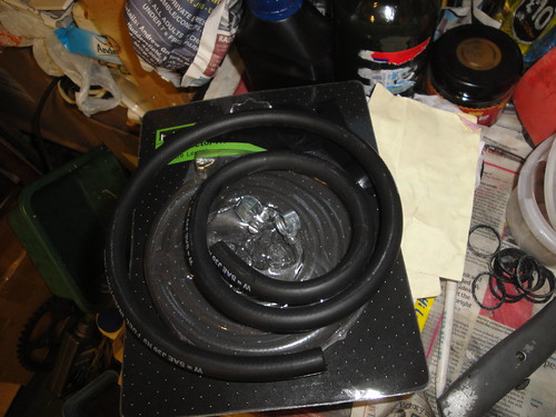
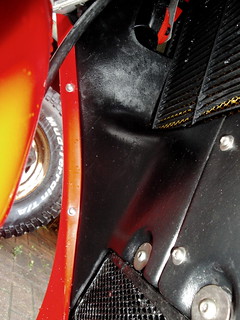
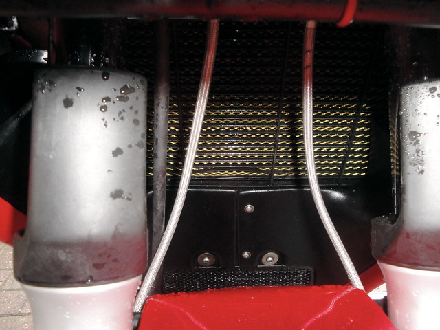
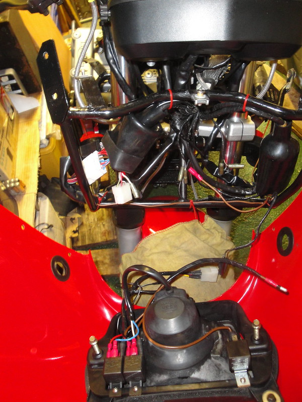
The fuel injection hose is double walled which means it is robust and will resist kinking. The downside is that they won't tolerate tight bends. I allowed about 5cm of extra length on each pipe, plus the fuel filters each being about 5cm long, to accommodate the wider turns the injection hose would need. There is plenty of room around the front and rear sides of the petrol tap. Unfortunately, the same is not true to the rear of the tap where one of the hoses and a vacuum line attach. Judicious juggling and careful routing of the main wiring harness are needed to make it work. More on that later. The additional length of the hoses means that I can uncouple the low fuel sensor wire, release the front of the petrol tank and rotate it 180 degrees to rest on the rear subframe for engine testing and tuning.

In-line fuel filter fitted to new hose
That's right: the startup moment is upon us.